The Eight
Control Project
Internet communication between Android and Arduino
by Klaus Pintoffl
General information
Eight Control is an IP based remote control for home. You can
contol anything like light, doors, home appliances. Eight control
consists of two parts: A program for an Android phone or
tablet, used as the remote control unit. And an Arduino Ethernet
board (or Arduino Ethernet shield and an Arduino board with an
Atmega 328 processor) as the receiver - which is connected to
your home network router.
You can control a total of 8 channels, over the home network or
over the internet.
To set up the Arduino server, some computer skills or will to learn are required.
The author does not take responsibility for any damage,
injury, malfunction, malicious attack, or other risks associated
with this application or any electrical installation.
While the phone options are configurated on a setting page (technically:
shared preferences), the server is configured via a text file on a
micro-SD card (Arduino ethernet shield and Arduino Ethernet both have a
built in card reader!). This eliminates the need to change the Arduino code for the user!
You will have to connect the output pins of the Arduino board to
(usually quite inexpensive) relais boards, in order to switch
on and off devives that need more current than simple LEDs. LEDs can be connected directly, ideal for testing purposes.
If you are looking for an home automation system app with multi-user
capabilities, control over 28 output pins, and nearly no setup on the
mobile device, you might want to take a look on my other application,
Home Ctrl 28 (which might offer much more than you need!) http://klaus30.bplaced.net/homectrl28/index.html
History
Version 1.3: First released version. Added End User Licence Agreement.
Version 1.4: Released July 8th
2012. Support for Android 4.0 an above. Functionality to select phone
or tablet UI style (4 functions per page and fling to change to
functions 5-8, or all 8 functions or one page) in Settings. In Android
4.0 and above, the OS version can no longer be used to determine tablet
or phone.
Version 1.5: Released July
26th. Multiple data values can be transmitted and displayed on the
phone/tab. Names for first 4 values can be set up in application, all
subsequent values get named Value 5, Value 6...The Update/Temp button
in options menu was renamed to Data/Update.
Version 1.6: 2 bugfixes: 1.
Reported crash due to underlocked wake lock (fixed). 2. Dialog box to
read data from server reappeared when it was last active, and app was
brought to background by home key or settings page (fixed).
EightControl7 (Arduino software): Release November 10 2012: 2
bugfixes applied to Arduino Server software: 1. MAC adress was not
correctly read from SD card, causing problems on some networks (fixed).
AES key not correctly read from SD card, user reported inability to
switch functions (fixed). Reading parameters from SD card are no longer affected by carriage return at end of line.
Android Application
After starting up Eight Control and accepting the end user agreement,
four control functionscan be seen on your Android phone. Flinging down
the finger (on the area right to the buttons, as if you were lighting a
match) takes you to functions 5 to 8. On an Android tablet, due to the
larger screen estate, all 8 functions are located on one screen. Users
can set up the button text and a description for each function. Buttons
can be hidden from the user interface individually (in case you for
example only need to control 1 or 2 functions). All
function buttons are triggered on long press, to avoid
unwanted activation - place one finger softly on the buttons for about
one second! Below is a screenshot of the user interface on the phone (fling down for next 4 functions) and tablet.
Eight Control 1.3 automatically
switched between the phone- and tabled based user interface. As
Android 4.0 and above runs on phones and tablets alike, the OS is no
longer used to select the interface automatically. In Eight Control 1.4 (released July
8th 2012) users can choose between both interfaces (Settings -->
Application --> Phone/Tablet Style).

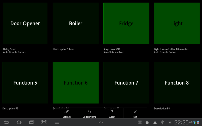
The option menu is self-explaining.
Since Version 1.5, multiple Server side data values can displayed
on the phone/tablet. The names of first four values can be set up in
the Application settings. If the Arduino Server transmits more than 4
values (the number is not limited) these will get named Value 5, Value
6 and so on on the phone. To transmit values, follow the comments in
the Arduino code. Basically, in the correct place, make all necesary
analog pin readings and/or float/int calculations. Send the value with
client.print(value); Separate from next transmitted value using
client.print"_"; Do not send text strings, this could interfear with
the aplication. It all sounds more complicated than it is, just take a
look at my Arduino code comments and 3rd screenshot below.


Network
Setup:
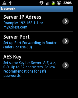
Set the IP adress of your
Arduino Server. Inside your own home network, use the IP adress of
your Arduino server (same as in the Settings text file on the SD
card). When you connect over the internet (outside home network),
you have to use your external IP
adress. If you google "my IP adress", you will find
sites to display your current external IP adress. If you have a
dynamic (changing) IP adress, there are online services available to solve
this problem.
Server Port:
Only needed to connect over the internet. If you use anything other
than 80 (Port 80 is open by default, but less safe) you have to
configure port forwarding on your router. Sites like portforward.com
can help with this. 80 is set by default, it is good for use within
the home network, or for testing (or non-critical functions).
AES Key: Use 32 characters
(A-Z, a-z, 0-9) for this key. You can use less, but then it is less
safe. You can use more than 32 characters, but everything over 32 is
ignored. Least safe would be your first name and birthday. You have
to set the same key in the Settings text file on the server SD card!
Application Setup and Login screen:
Phone or Tablet style: Set the user interface to accomodate phone or tablet screens.
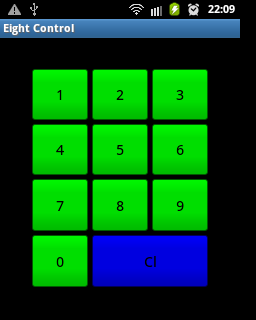
Application code: A code to
protect the Eight Control application. If you borrow your phone to
others, you do not want them to use Eight Control. Remember this code, you need it
to log into Eight Control!
Use Application Code: If
this checkbox is selected, the Application code has to be entered
the next time you start Eight Control (screenshot below). Make sure
to remember the code, otherwise you have to de-and reinstall Eight
Control, and all settings would be lost.
Auto Refresh Interval:
Wall-mount a cheap Android Phone and have the User Interface update
periodically. A Wake-Lock will prevent the phone/tablet from
sleeping- so make sure external power is connected. If set to off,
no data will be transmitted to to or from the server, unless a
function is executed.
Auto Close Program: If
selected, the application closes automatically some seconds after a
function was executed. You do not need to exit the application
manually.

Function
Setup:
All 8 functions have the same (extensive) set of options.
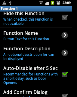
Hide this Function: The
dunction is not displayed on the user interface (many people just
need one or 2 functions, not all 8).
Function name: The
text displayed on the button. Could be "Door opener", "Garage",
"Light" or similar.
Function description: Right
to each button, an optional description can be displayed (on a
tablet underneath the buttons).
Auto-Disable after 5 Sec:
If you control a door opener, you might want to set a short delay (e.g
3 sec) on the server. Executing the function turns the relay on for 3
seconds. Usually the user interface would display the function is still
on until updated. But when the Auto-Disable option is on, the android
button returns to release state after 5 seconds- without reconnecting
to the server! The actual delay for an output pinin seconds has to be
set on the server using the Settings.txt file (see below)!
Add confirm Dialog: For
sensitive functions, a kind of "do you really want to" Dialog is
displayed. If you do not confirm within some seconds, the function
will not be executed and the dialog disappears. I use this for the
door control.
Server
Output
pins:
Eight Control uses up to 8 pins as output for relais cards (or to
switch on and off LEDs). In the Arduino code, these pin numbers are
defined in an array:
int outPins[] = {9,8,7,6,5,3,2,1,0};
Position 0 of the array (Pin 9), defines a LED that blinks after the
program has started successfully. No need to connect one, but it is
already integrated on an Arduino Ethernet.
Channel 1 (Pin 8 on the board) is the first channel (the one
controled with the 1st button, or Function 1, on the mobile
application.
Channel 2 (Pin 7 on the board) is the second channel (the one
controled with the 2nd button, or Function 2, on the mobile
application.
Channel 3 (Pin 6 on the board) is the 3rd channel (the one controled
with the 3rd button, or Function 3, on the mobile application,
and so on.
The pins not mentioned here (13, 12, 11, 10, 4) are used by the
electronic circuit (communication between the processor, and the SD
card and ethernet chip).
Here is the complete output pin table:
Channel number on
phone or tablet
|
1
|
2
|
3
|
4
|
5
|
6
|
7
|
8
|
Board pin
|
8
|
7
|
6
|
5
|
3
|
2
|
1
|
0
|

Settings.txt File:
The microSD card must contain a text file named
"Settings.txt". This file contains multiple lines that are used to
configure the server. When the server is powered, it reads the
configuration of this file, and then commences his actual work of
listening to your android devives. A Settings.txt file
looks like this (you can copy and paste and then make your changes):
IP=192.168.1.3
MAC=0x60-0xA3-0xBA-0x01-0x7D-0x33
Port=50055
Gateway=192.168.1.1
Subnet=255.255.255.0
Key=rAndom32CharactersLOnG
Delay1=3
Delay2=3600
SaveState=357
The first line is the IP
adress of the server within your home network.
The second line is a MAC adress.
You can use any, but all MACs must be different within a network. A
sticker on your board is a recommendation. You have to define a MAC
adress here.
The next line defines a Port,
used to connect over the internet. The same port has to be set on
the mobile application (Network Setup), and has to be forwarded in
your Router. If you want to avoid setting up port forwarding in your
router, you can use port 80. 80 is a standard port, and it is less
secure to use it.
Line 4 and 5 are gateway
and subnet settings of your home network. You get them by
typing" ipconfig" on the command line of a windows PC in the same
network.
Line 6 is the encrypion key,
that also has to be entered into the android device. This key
determines the safety of Eight Control. It should be up to 32
characters (the longer the better), and a random combination
containing A-Z, a-z, 0-9.
The next lines are used to set
delays to your functions: Delay1=3 means that if Function 1
is pressed on the android phone, the relay on the server (on board
pin 8) switches on for 3 seconds. I use this for a door opener.
Delay2=3600 means Function 2, if activated, turns on and switches
off automatically after 1 hour. You can specify Delay3 to Delay8 in
the same way (one line for each delay used). Functions for which no
line exists stay on until switched off by the user.
The last line (SaveState) defines which function states are remembered by the server.
SaveState=357 means that Functions 3 and 5 and 7 will, after a power
down, automatically return to the state they had before (go to on if
they were on, off if they were off). This makes sense if you e.g
control a fridge. You would however not want to use it for a TV or
door opener. For SafeState, only one line should be used in the
Settings.txt file, as there are no function-specific parameters.
Download an example Setup file here: Setup.txt
Programming Process
Hardware:
As hardware components, you have 2 options (refer to http://arduino.cc/en/Main/Hardware
for more information on these parts):
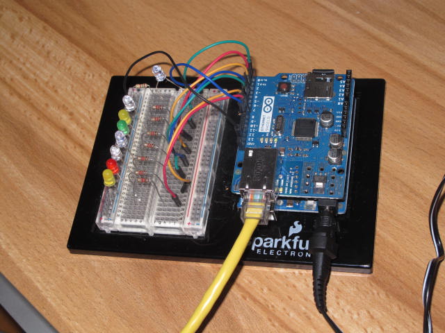
Option 1: Use an Arduino Ethernet
Board. This contains the Atmega microcontroller, an microSD card
reader and an ethernet card. Programming is possible using an ISP
programmer or an FTDI USB cable. Option 1 is more compact, as it
only consists of one single board. However, you need an FTDI USB
cable or and ISP programmer to load the program into the
microcontroller. This is because the board has its Ethernet
connector in the place of an USB connector.
Option 2: Use a Arduino Ethernet shield on top of an Arduino with
ATmega 328P microcontroller. Programming in this case can be done
using USB or an ISP progammer. Option 2 is your best bet if you
just get started with Arduino, as you can upload the program using
USB (no extra hardware needed).
Here is a screenshots for each of the 2 options:

The following is a step-by-step
instruction on programming the server using Option 2
(getting the Eight Control program into your microcontroller via USB
connection).
1. Download Arduino 1.0.1 from the download section of the Arduino
website http://arduino.cc/en/Main/Software.
I have recently tested versions 1.0.1 and 1.0.2 on Ubuntu Linux. You do not have to install the software, just unzip
it and everything you need is within the arduino-1.0 directory.
2. Download EightControlFiles.zip
and unzip it to a new directory.
3. Copy the two directories "AES256" and "Timer1" into the libraries
directory of arduino folder
(The third directory, EightControl3, contains the Arduino server
source code needed in the next step).
4. Start the Arduino software (Arduino.exe on Windows, arduino shell
script on Linux), select
File-->Open-->EightControl3/EightControl3.ino.
5. Stack the Ethernet shield onto the Arduino board (see image
avove). Connect the Arduino board to the PC via USB.
6. In the Arduino IDE, select your board under
Tools-->Board, and your USB
Port under Tools-->Port.
7. Use the checkmark button (under menu bar) to compile the code. If
it compiles without any error, all libraries are installed
correctly. Press the arrow
button to upload the program to the Arduino board.
8. Write a Settings.txt file to a micro SD card's root directory,
see the Server section above.
9. Connect the new Arduino server to a router, and to an external
power supply. You should now be able to control the output pins with
EightControl on an android device.
The EightControl software features
a Watchdog timer to automatically restart the server after 8
seconds of unresponsiveness (though this has never happened
in my tests and use). The Watchdog is, however, disabed by
default, as it is not compatible with the Arduino bootloader. If
an ISP programmer is used (this deletes the bootloader), Watchdog
can be enabled by setting boolean watchdog = true in the line of
sorce code below (at the end of the setup fuction). There is an
great article on Watchdogs: http://www.ganssle.com/watchdogs.pdf
//set false if Arduino with
bootloader used (conflicts)
boolean watchdog = false;
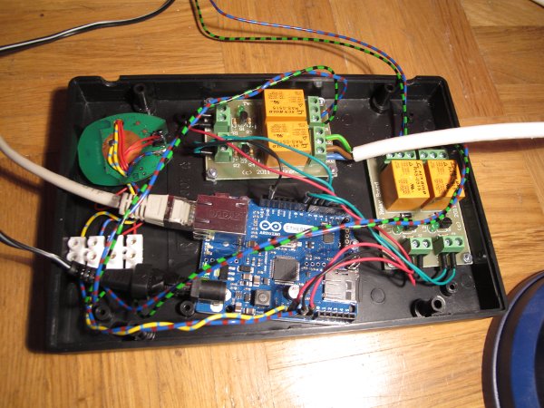
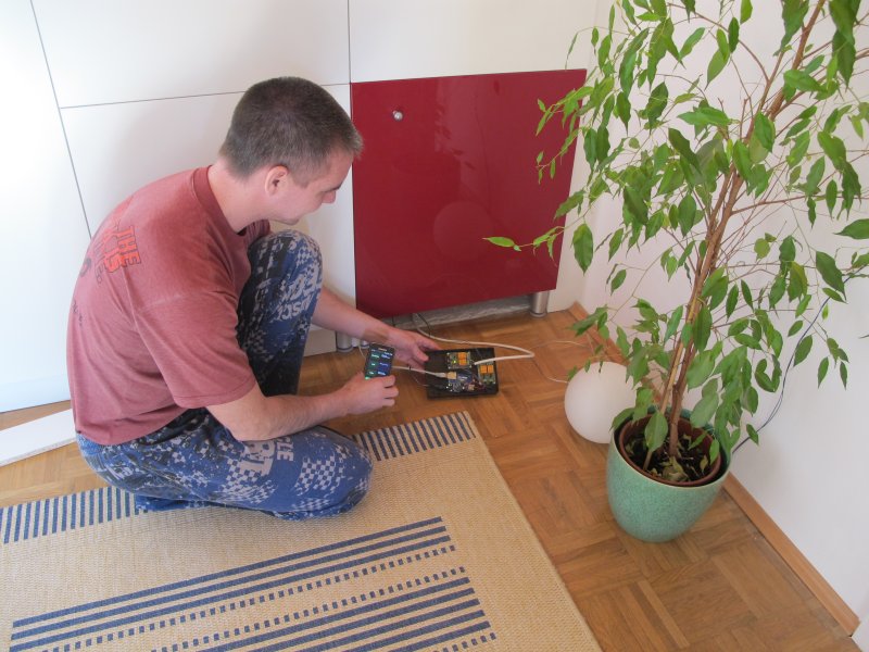
The image below displays myself performing the final installation of
the server unit. I am now able to control the main door and some
lights in my home, convieniently from an Android phone or tablet. If
someone comes to see me, I don't even have to get up from the sofa
any more!
Good luck and have fun with Eight Control!
Downloads
EightControl.zip
contains the EightContol Arduino project, and additional libraries
needed.
Settings.txt is an
example configuration file. It is needed on the SD card of the
server.
Installing a door opener
This section shows one "interpretation" of an eight-controlled door
opening system. The system used is inexpensive and can lock/unlock
doors without the hassle of cables, as both parts are battery
opereated. The lock actuator is mounted on the inside of a door
(over a physical key which is turns). The only requirement is a
cylinder lock of correct dimensions, and with emergency operating
feature (keys can be turned from both sides at the same time).
To be honest, I was not too sure this would work out, but this
remote control has an incredible will to survive. After the
modifications, I powered the remote unit from the Arduino's 3.3
Volts pin. See the images below.


